1INTRODUCTION AND GOAL
Svenska Kraftnät is developing Technical Guidelines with requirements for composite insulators for 220 kV and 400 kV AC overhead lines. These guidelines should guarantee required performance of composite insulators during the estimated technical lifetime of the overhead line and shall be used for purchasing of composite insulators. At present SvK’s typical overhead AC lines for 220 kV and 400 kV are equipped with strings of cap-and-pin insulators protected by arcing horns. Composite insulators normally require more protection, both from corona and arc protection point of view. Thus, the question arises on how to optimize the existing arcing horns to fulfil the following:
*Power arc protection *Limitation of E-field at the sensitive part of the composite insulator from water drop corona point of view *Elimination of visible corona from the corona/grading ring. The goal of the project is to issue practical recommendations for geometrical dimensions of arcing horns/corona rings for 220 kV and 400 kV to be used as a basis for developing Technical Guidelines for composite insulators. In particular, double tension strings with composite insulators are of primary interest to Svenska Kraftnät. The present paper concentrates E-field criteria and calculations.
2 CRITERIA FOR CALCULATION
Calculation of E-field includes evaluation of two critical issues:
Absence of water drop corona at sensitive vertical parts of composite insulators close to the lower fitting (in the following review this issue is called “Maximum E-field stress at composite”) Absence of visible corona from the corona/grading ring (in the following review this issue is called “Maximum E-field stress at metal”) 2.1 Review: Maximum E-field stress at composite There is no much data published on this criterion. In CIGRE Brochure 284 [1] calculations at the tip of the first shed from the fitting performed as an example in led to levels of 6-10 kV/cm, which in the opinion of the authors of this report are too optimistic. Recent EPRI research indicates that limiting the maximum value to 4,5 kV/cm is preferable [2]. Actual field magnitudes on the rubber surfaces of composite insulator sheath sections may vary considerably depending on the design, configuration and application [2]. A value of about 3,5 kV/cm was proposed at STRI as the threshold E-field stress, see data for corona inception in Figure 1. It was shown that this value depends upon the hydrophobicity properties and insulator profile (mainly the distance between sheds).
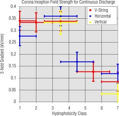
Figure 1: Examples of STRI findings based on small-scale laboratory experiments in a uniform E- field gap.
The type of insulator, grading rings, tower framework, yoke plates, and conductors were simulated in a Chinese paper comprising calculation of the E-field distribution on composite insulator for 1000 kV AC [3]. The calculation was performed as a 3-D open-boundary problem and the results are shown in Figure 2, from which critical E-fields about 3,8 kV/cm can be estimated. If a grading ring is properly selected (leading to a maximum E-field stress of about 3 kV/cm in the air close to the sheath), also the temperature increase associated with high E-field stress will be avoided as reported in [4].
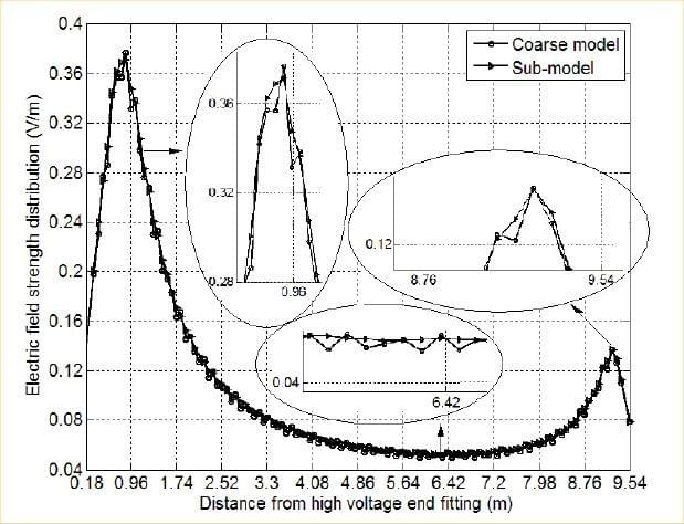
Figure 2: Example of findings adapted from [3]: E- field distribution along the 1000 kV insulator.
2.2 Review: Maximum E-field stress at metal surface Concentrating on corona from metal parts, CIGRE Brochure [1] recommends the limit 22 kV/cm. Of course, corona issues and arc protection should be coordinated via RIV test of complete configurations [4]. According to [2] the value indicated for surface E-field on the metallic end-fittings and corona rings is 21 kV/cm and is often used as a reference value for design purposes. According to internal CIGRE discussions some utilities use values as low as 17
kV/cm. This is probably to account for corona activity from water drops on the metal hardware surfaces, or ageing of the corona rings.
2.3 Final criteria Based on literature research, and some design practice the design of corona rings should be based on the following criteria:
E-field on the metal surface of corona rings/fittings ≤ 18 kV/cm
Tangential component of E-field along the insulator surface ≤ 4 kV/cm.
3 , MODELLING
E-field calculations were performed with the Finite Element Modelling (FEM) tool Comsol Multiphysics ver. 3.5a. Electric fields were calculated using 3-D models. By doing this. the electric field can be calculated taking into account the effects which could not be included in a 2-D axis-symmetric model, such as the tower and the conductors. A general 400 kV tower model is shown in Figure 3. The calculations were performed for the middle phase (worst case), see Figure 4. The insulator was more carefully modelled closer to the fittings, since these parts have a greater influence on the E-field distribution. The size of the finite-element mesh was reduced in the areas of interest. The cube in Figure 3 defines the volume with extra fine mesh. By doing this, the electric field at relatively small parts of interest can be resolved within a reasonable computation time. The silicone sheds are included only in proximity to insulator ends, where the field is expected to be the highest and thus needs to be modeled accurately. This allows reducing the required number of elements in the model and consequently reducing the computational time. The electric field strength is generally higher at the high voltage side of the insulator, than at the grounded side. Thus, the end-fitting of the insulators at the conductor side were modeled accurately, while at the tower side a more simplified geometry was used.
The dimensions and position of the rings are defined by the following parameters: R – Inner radius of the ring; ø – Diameter of ring cross- section; d – Ring location along the insulator. It is measured as the distance from the end fitting collar to the ring center lines (see Figure 5). In cases where the end fitting is molded in the silicone rubber, d refers to the distance from the metallic collar of the fitting inside the mold.
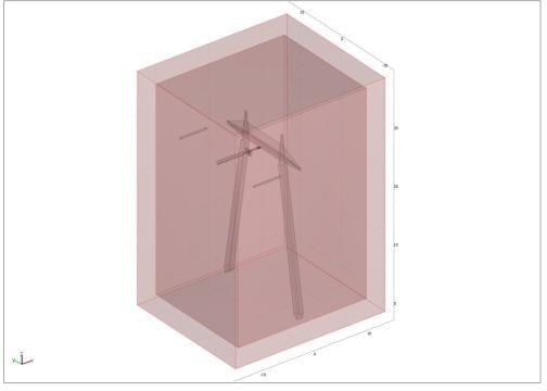
Figure 3: 3-D model of line tower with tension insulators.
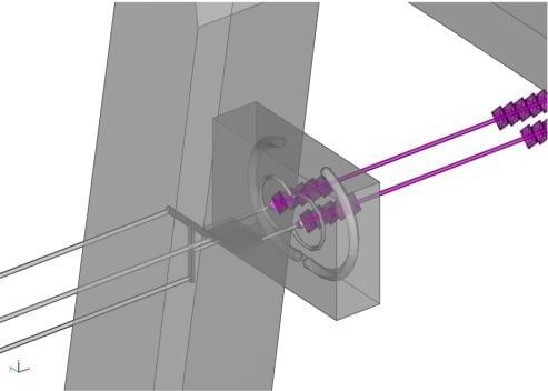
Figure 4: Detail of 3-D line tower model with tension insulators.
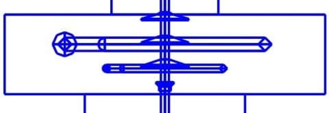
Figure 5: Definition of distance d between fitting collar and ring centre lines.
4 . SELECTION OF INSULATORS FOR CALCULATIONS
In order to cover a broad range of existing composite insulator designs, there was chosen four “typical” examples of designs to represent, especially, different end fitting types (Figure 6):
Design 1 equipped with typical spherical extension at the live end fitting. Design 2 with just slightly rounded live end fitting. Design 3 with the live end fitting completely covered by the silicone rubber. Design 4 with the live end fitting partly covered by the silicone rubber.
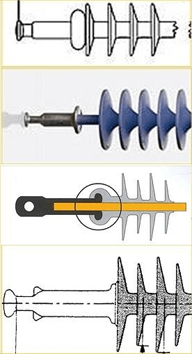
Figure 6: Examples of four typical end fitting designs.
5, INITIAL CHOICE OF CORONA RINGS
A calculation of E-field started from the existing design of corona rings/arcing horns for 220 kV and 400 kV; these designs are summarized as follows. For 220 kV there is one corona ring from HV side with inner radius (R)/cross-sectional diameter (ø) 170/28 mm. For 400 kV a larger corona ring is placed from HV end (R/ ø=350/76 mm) and a smaller is at the grounded end (R/ ø=205/28 mm).
6, CALCULATIONS FOR 220 KV
E-field calculations were performed for a few types of insulators listed in Section 4. The results of calculation showed that a single 170/28 mm ring at the HV end of the insulator results in a maximum tangential field on the insulator surface in the range 2,5-3,4 kV/cm for the different insulator types under study. The difference depends on the end fitting design used by the respective manufacturer. The values are in all cases below the recommended limit 4 kV/cm, while the E-field at the ring surface is close to the recommended limit 18 kV/cm. Thus, no issues are foreseen for 220 kV when replacing glass cap-and-pin insulators strings with composite insulators strings. Examples of calculations are given in Figure 7- Figure 9.
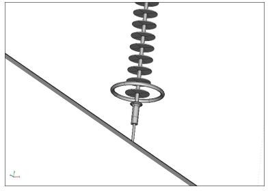
Figure 7: Geometry of the lower part of an insulator 220 kV with one corona ring
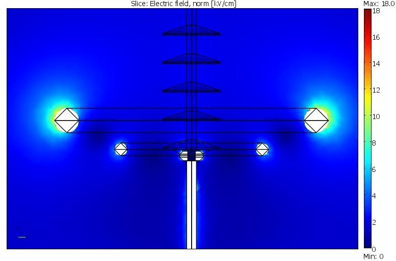
Figure 8: Electric field strength on metal surfaces.
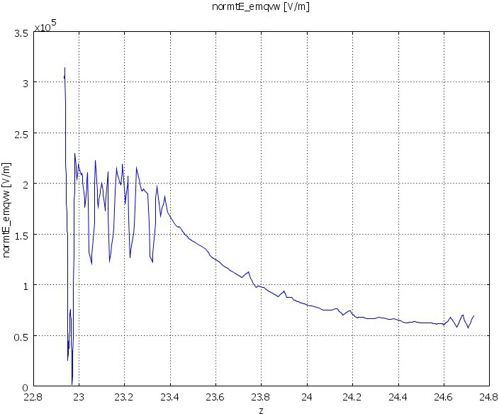
Figure 9: Tangential component of the electric field along the insulator length. (Left part of the diagram – insulator’s HV end, right side – grounded end).
7 . CALCULATIONS FOR 400 KV
This voltage class was of primarily interest and thus calculations included three different steps. In the first step, calculations were performed for all insulator designs listed in Section 4 mounted as suspension insulators. These calculations showed that there is a need of double corona rings from the HV end, examples for one of insulators see in Figure 10-Figure 12. The results of calculation showed double corona rings at the HV end of the insulator results in a maximum tangential field on the insulator surface in the range 2,2-3,2 kV/cm for the different insulator types under study. The difference depends on the end fitting design used by the respective manufacturer. The values are in all cases below the recommended limit 4 kV/cm, while the E-field at the ring surface is close to the recommended limit 18 kV/cm. Further sensitivity analysis was performed for slightly different positions and dimensions of corona rings. Calculations were also performed for open geometry rings (to check the E-field limits at the surface) and for double tension string arrangement (see Figure 13-Figure 15), which also fulfilled the criteria for E-field.
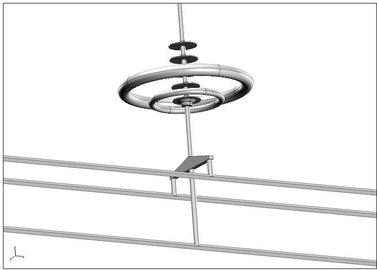
Figure 10: Geometry of the lower part of an insulator 400 kV with double corona rings.
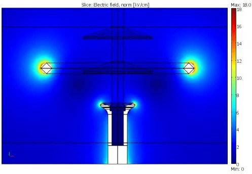
Figure 11: Electric field strength on metal surfaces.
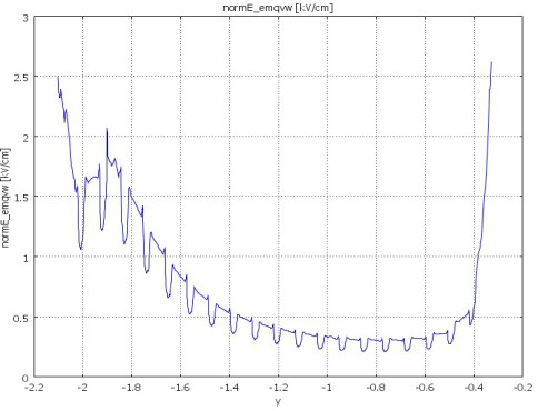
Figure 12: Tangential component of the electric field along the insulator length. (Left part of the diagram – insulator’s HV end, right side – grounded end).
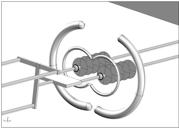
Figure 13: Geometry of the double tension string 400 kV with double opened corona rings.
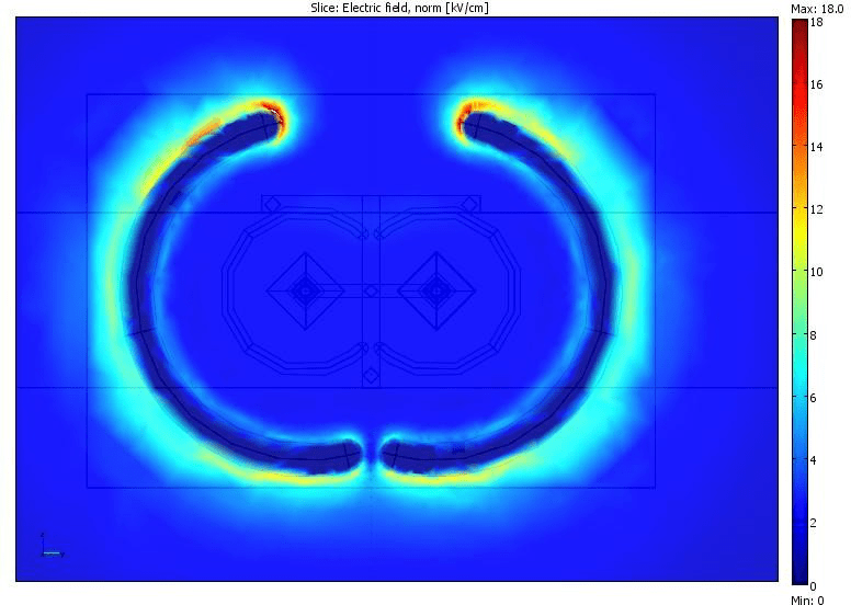
Figure 14: Electric field strength on metal surfaces of larger corona ring.
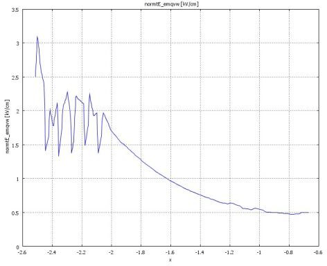
Figure 15: Tangential component of the electric field along the insulator length. (Left part of the diagram – insulator’s HV end, right side – grounded end). Additional calculations were performed for the simulation of open arcing horns with a sphere connected to the end of the larger one (Figure 16-Figure 17). The highest field strength on the surface of the both arcing horns is about 14 kV/cm (at the sphere 17,4 kV/cm). The highest calculated tangential component of electric field along the surface of the insulator rod is ~2,5 kV/cm at the HV end and ~1,9 kV/cm at the grounded end, well below the chosen criterion.
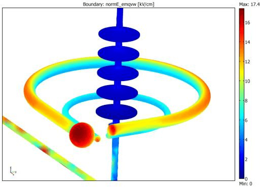
Figure 16: Electric field strength on metal surfaces of open arcing horn.
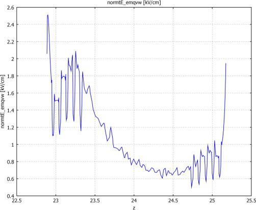
Figure 17: Tangential component of the electric field along the insulator length. (Left part of the diagram – insulator’s HV end, right side – grounded end). Horizontal scale shows relative coordinates along insulator (in meters).
Finally, for 400 kV insulators the results of calculations showed that a 350/76 mm ring together with a 200/40 mm (or a 205/28 mm) ring at the HV side of the insulator string result in a maximum tangential field on the insulator surface in the range 2,2-3,2 kV/cm for the four suspension insulator types under study, which is well below the recommended limit of 4 kV/cm. As for 220 kV, the noted differences depend on the end fitting designs.
As shown from the calculations on the detailed model of the open ring for double tension insulator, the E-field at the ring surface is close to the recommended limit 18 kV/cm. The complementary calculations show that the 76 mm ring diameter can be decreased to 50 mm in combination with a ball diameter of 110 mm, without exceeding the recommended limit 18 kV/cm for the metal surfaces.
Thus, no issues are basically foreseen for 400 kV, when replacing glass cap-and-pin insulators strings for composite insulators strings.
8, CONCLUSIONS
The basic requirement from SvK was to investigate the possibility of using as much as possible the existing hardware (arcing horns) for applications with composite insulators. The results from the E- field calculations show that this is a feasible approach.
Based on the results of calculation, the specific design recommendations are given for arcing horns/corona rings on composite insulators at 220 and 400 kV. The recommendations apply to all types of composite insulators that have end fitting designs similar to the types covered in this report.
For 220 kV only one ring at HV side is needed and the ring dimensions should be 170/28 mm (vertical location is also defined). No ring is needed at the grounded end from the point of view of corona or voltage grading, but may be needed for arc protection.
For 400 kV double rings are needed at HV end. The larger ring dimensions should be 350/76 mm, or 350/50 mm in combination with a 110 mm ball. The smaller ring should be 205/28 mm. Vertical locations of rings are also specified. No ring is needed at the grounded end of the insulator from the point of view of corona or voltage grading, but should be applied for arc protection.
The same recommendations apply to both suspension and tension strings, although half-rings should be used for the double tension strings.
To verify the final dimensioning of corona rings/arcing horns for 400 kV, full-scale RIV tests may be proposed. The arc test is optional.
9REFERENCES
[1]CIGRE Brochure 284: “Use of corona rings to control the electrical field along transmission line composite insulators”, December 2005 [2]A.J. Phillips, et al.: “Electric Fields on AC Composite Transmission Line Insulators”, IEEE Transactions on Power Delivery, Vol. 23, No. 2, April 2008, p.p. 823-830 [3]Daochun Huang, Jiangjun Ruan, Yong Chen, Feng Huo, Shifeng Yu, Shobao Liu: “Calculation and measurement of Potential and Electric Field Distribution along 1000 kV AC Transmission Line Composite Insulator”, Electrical Machines and Systems Conference, ICEMS-2008, 2008, p.p. 428-433 [4]I. Gutman, K. Halsan, L. Wallin, T. Goodwin, G. Sakata: “Application of Helicopter-Based IR Technology for Detection of Internal Defects in Composite Insulators”, World Congress &
Exhibition on Insulators, Arresters & Bushings, Crete, 11-13 May 2009 [5]CIGRE Brochure 365: “On the use of power arc protection devices for composite insulators on transmission lines”, December 2008
