
Our insulators advantage:
Explosion-proof: The core material of these composite insulators for substations is fiber-reinforced polymer (FRP). High-strength glass fibers run throughout the structure, providing exceptional strength and toughness. In the extreme event of excessive internal pressure, the insulator will not explode; instead, it will crack, allowing pressure to be released through the fissures and effectively preventing casualties.
Fracture-resistant: These insulators help prevent damage during seismic events. The FRP core contains approximately 80% glass fiber, arranged in a cross-linked, grid-like structure through varied layering. This design ensures the entire component bears the load, significantly enhancing the mechanical strength and toughness of the FRP material—under extreme stress, it may develop cracks, but it will not fracture completely.
Flashover-resistant: The high-temperature vulcanized (HTV) silicone rubber used is a hydrophobic material with excellent water-repellent properties and the ability to maintain this hydrophobicity over time, effectively preventing pollution-induced flashovers. The material also exhibits favorable thermal characteristics; during freezing rain or snow, it prevents the formation of long icicles. Even if short icicles do form, they do not pose a risk.
30-year maintenance-free: The silicone rubber contains a high concentration of small organosilicon molecules that continuously migrate to the surface, covering any accumulated pollutants and imparting water-repellent properties to the pollution layer itself. Throughout their entire service life, these composite insulators require no cleaning, washing, or application of RTV (room-temperature vulcanizing) coatings, resulting in significant savings on operation and maintenance costs.
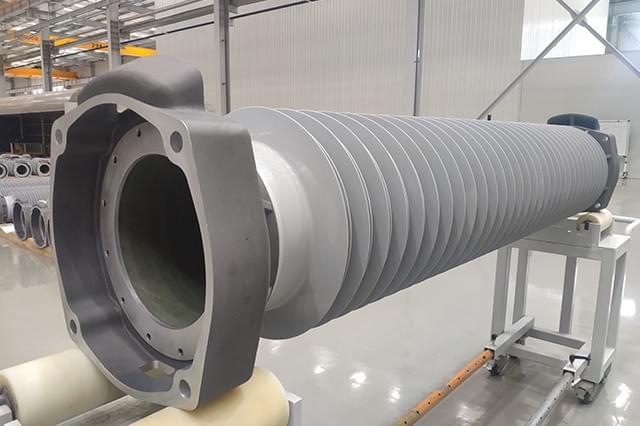
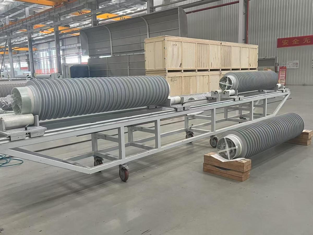
A hollow composite insulator is a key insulating component used in high-voltage electrical equipment, characterized by a hollow core that distinguishes it from traditional solid-core insulators. It is essentially a strong, hollow tube made of composite materials, designed to provide both mechanical support and electrical insulation.
🏗️ Core Structure and Materials
The construction of a hollow composite insulator is a composite of three main parts, each with a specific function:
Load-Bearing Insulating Tube: This is the structural heart of the insulator. It is typically made from resin-impregnated fibers, most commonly glass-fiber reinforced epoxy (FRP). This tube provides the necessary mechanical strength to support the connected equipment, and its hollow design allows for other components or gases to pass through.
Housing (Sheds/Sheath): The outer layer is an elastomeric housing, usually made of silicone rubber or ethylene-propylene rubber. This housing, including the sheds (the ribbed structures), protects the inner tube from environmental factors like moisture, pollution, and UV radiation. It also provides the critical hydrophobicity (water-repellent property) needed for reliable performance in wet and dirty conditions.
Metal End Fittings: Metal fixing devices (flanges) are attached to both ends of the insulating tube, allowing the insulator to be securely connected to other high-voltage apparatus.
🔍 How It Differs from a Solid-Core Insulator
The defining feature is, of course, its hollow core. This is not just a structural difference but one that brings specific performance advantages:
Structure: A solid-core insulator has a dense, solid rod (often also FRP) as its central load-bearing element. A hollow-core insulator, as its name implies, has a tubular core.
Mechanical Performance: The hollow cylindrical shape is particularly effective at handling high bending moments with relatively low deflection. This makes hollow composite insulators well-suited for high-voltage applications (e.g., above 245 kV) where large cantilever loads are a concern.
Functionality: The hollow interior can serve a functional purpose. For instance, in circuit breakers, the hollow core often houses SF₆ insulating gas or other arc-quenching media, a role a solid core cannot fulfill.
Weight: While both are lighter than porcelain, the hollow design can contribute to weight savings, especially in very high-voltage equipment where reducing the overall weight of the apparatus is crucial.
✨ Key Advantages
Compared to traditional hollow porcelain insulators, composite hollow insulators offer several significant benefits:
Superior Safety: They are less prone to catastrophic failure. Unlike porcelain, which can shatter explosively, the composite materials typically fail in a less violent manner, reducing the risk of injury or damage to nearby equipment.
Excellent Pollution Performance: The silicone rubber housing provides outstanding hydrophobicity and hydrophobicity transfer, meaning it repels water and can even transfer this property to surface contaminants. This results in excellent resistance to pollution flashover, making them ideal for heavily polluted or wet environments.
Lightweight and Compact: They are significantly lighter than porcelain equivalents (approximately 1/7 to 1/3 the weight), which simplifies transportation, installation, and reduces the mechanical load on the supporting structures.
Reliable Sealing: Advanced sealing structures between the tube and metal fittings ensure high reliability, preventing moisture ingress which could compromise the insulator's internal insulation.-21
⚡ Primary Applications
Hollow composite insulators are integral to a wide range of high-voltage equipment, generally for systems with rated voltages above 1,000 V AC or 1,500 V DC. Common applications include:-2
High-Voltage Circuit Breakers
Disconnectors and Switch-Disconnectors
Instrument Transformers (current and voltage transformers)
Power Transformers and Bushings
Cable Terminations
Surge Arresters
Station Posts
In summary, a hollow composite insulator is a modern, high-performance alternative to traditional porcelain hollow insulators, offering a combination of safety, excellent pollution resistance, lightweight design, and the unique ability to serve functional roles like housing insulating gas within high-voltage electrical apparatus.
Application A: Composite Hollow Insulators
• Addition vulcanizing (platinum catalyzed) silicone systems are replacing peroxide curing systems. Addition curing systems do not emit hazardous volatile compounds and are fully in compliance with REACH/SVHC regulations. This also applies for other polymeric materials employed.
• Life-cycle assessment (LCA), i.e. cradle to grave considerations, is required and must demonstrate all related efforts as well as net advantages and disadvantages – not only in terms of cost but also environmental impact.
• Alternative gases and their decomposition products must be considered and HCIs are equipped accordingly.
• With increasing demand for EHV, UHV and HVDC solutions, future composite insulators designs need to be realized in extreme dimensions, e.g. lengths over 12m and inner diameters larger than 1000mm. Suitable manufacturing processes will need to be developed or enlarged.
• Alternative gases show lower electrical strength than SF6 and this will mean higher internal pressures for insulation. HCI designs for such applications will need to accommodate higher maximum service pressures (MSP), according to IEC 61462, resulting in higher SIP as well as higher routine testing pressure (i.e. 2 x MSP). Designs will have to be upgraded to allow more robust, higher-strength insulators.
• The total cost of ownership (TCO) approach considers all parameters, not only the cost (price) of materials. OEMs/TSOs are increasingly adopting such a philosophy, which contains LCA assessment and a range of other input parameters resulting from SHE, handling and maintenance over the full service/operating life of HV apparatus.
• Aspects such as ‘hardening’ substations against terror attack are key promoters for application of HCIs at substations.
Application B: GIS Bushings
B. GIS Bushings
• Composite insulators will increasingly replace porcelain due to reasons on better pollution performance and safety.
• Alternative gases/dry air will replace SF6 due to REACH regulations.
• Achieving compact design given the lower electrical strength of alternative gases will represent a challenge.
• Electrical field grading/field control technology will be an effective design tool to reduce diameters and allow more compact bushing designs.
Application C: Composite Station Posts
C. Composite Station Posts
• Composite insulators will replace porcelain due to superior pollution performance and seismic resistance.
• Light weight, high-strength, and design as well as manufacturing flexibility are enabling application of CHSPs, with gas or foam filling media, for voltage classes exceeding 550 kV EHV AC, 800 kV HVDC and 1200 kV UHV AC.
• The ‘lifetime seal’ concept for CHSPs will help avoid need for expensive and vulnerable gas monitoring systems for gas-filled units.
• Over the next 20 years, composite station post insulators are expected to outperform and replace conventional ceramic insulators in all applications due to their economic, ecological and technical advantages. This also considers their evaluation according to the TCO model which includes initial product costs, supply chain, environmental requirements, maintenance, lifetime and risk assumptions.
Advertisement
Application D : Cable Terminations
Cable terminations for HVAC and HVDC are now increasingly important, especially in the latter case for marine and land cable transmission projects at 320 and 525 kV system voltage.
Technical expectations of these relatively new products including DC land cables and related joint and termination accessories is high, especially with regards to reliability and longevity. Nonetheless, experience is still limited for 525 kV such systems. The cable termination, for example, must be equipped with composite hollow insulators of large dimension in terms of diameter and length, e.g. the SOL cable termination for high pollution class has a length of 6500 mm. Terminations are filled with gas .
The reasons for choosing HCIs include:
• High-pollution resistance of their silicone housings;
• Oil-free designs offering no risk of explosion and/or oil contamination in case of failure such as from short circuit. Figs 4 & 5 show dry type and gas-insulated oil-free terminations. Filling can also employ alternative gases;
• High mechanical impact strength along with a non-critical failure mode (i.e. no burst or emission of sharp elements);
• Flexible length and diameter in design of the stress cone/field grading element
Cable Terminations
Modern cable terminations are oil-free (for safety and environmental constraints) and use either dry-type or gas-filled technology. Dry types can be realized with different technologies, based on the intellectual property of the manufacturer.
• Dry-types are replacing oil-filled, with gas filled insulation for higher voltage classes.
• Composite insulators will increasingly replace porcelain types due to SHE constraints.
• Plug-in technology for easier handling and installation is the trend since most failures are caused by improper connection and installation.
• Condenser style bushings (resin-impregnated condenser core – RIS/RIP style) are alternatives to gas-filled solutions and fall in the ‘dry type’ category.
Application E : Optical Instrument Transformers (ITs)
E. Optical Instrument Transformers (ITs)
Conventional instrument transformers (ITs) use SF6 gas or oil as insulating media to embed and isolate the transformer windings. This design principle has been proven for decades and is highly reliable. Over the past 20 years, however, a new IT principle has emerged based on optical physical effects.
Current transformers (CTs) have reached a high degree of maturity and acceptance by TSOs . The active optical CT head is placed on top of a hollow post insulator with optical fibers connected to it. The hollow post insulator acts as an optical fiber bushing accommodating a bundle of fibers internally embedded with a gas, liquid or polymeric insulation medium.
Similar optical principles are also used at HVDC converter stations and for monitoring/diagnostic purposes at substations and on overhead transmission lines (e.g. for temperature measurement, fault location, etc.). Insulation between high voltage (where the sensors are placed) and ground is realized by ‘signal columns’ which are slim HCI elements, typically as tension or suspension units.