
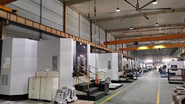
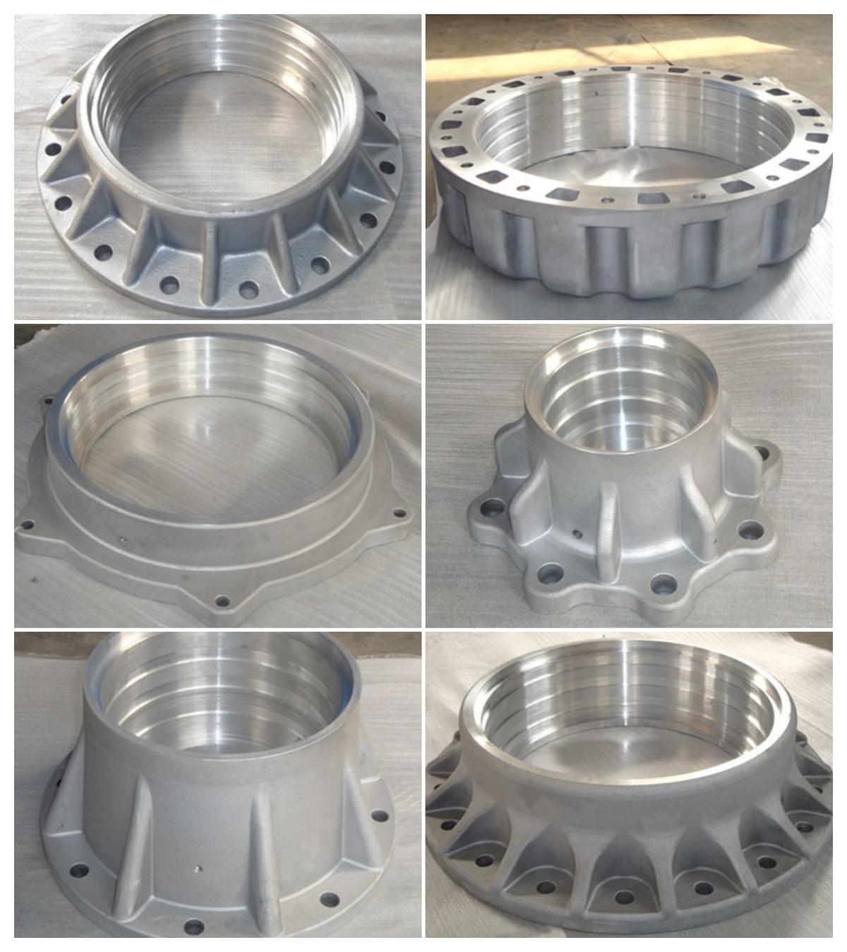
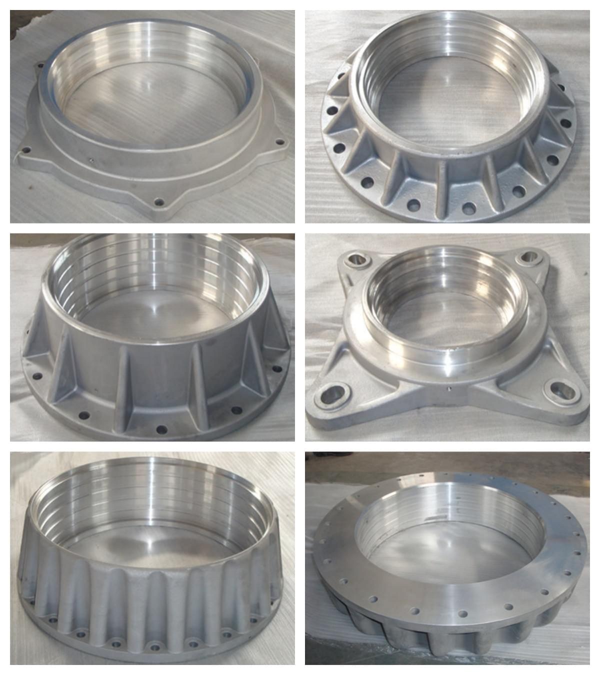
Оборудование высокого напряжения Производитель фланцев из алюминиевого сплава, литье под низким давлением деталей из алюминиевого сплава для высоковольтных втулок/композитных изоляторов/разрядников высокого напряжения
Электрические изоляторы алюминиевый сплав низкого давления литья, алюминиевый сплав 4/5 оси CNC обработки завод, ENAC-AlSi7Mg0.3-S-T6 EN 1706, AlSi10Mg, G-AlSi8Cu3, ADC12, A380/383, B390, A413, A356, сплав 443, A360

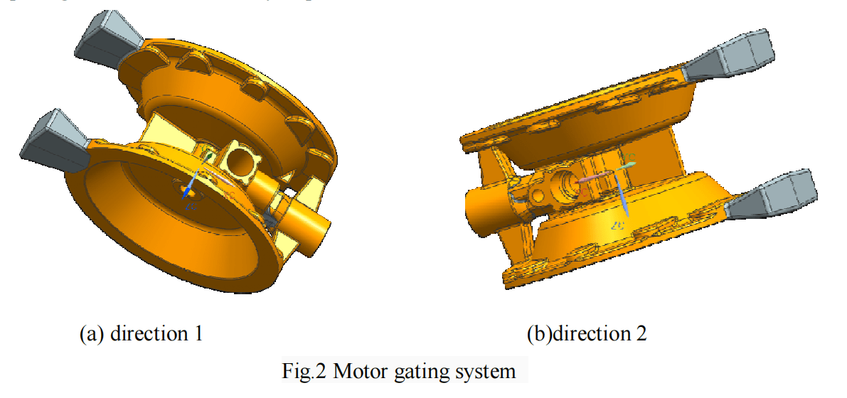
Технология литья под низким давлением двигателя из алюминиевого сплава
Ключевые слова: Алюминиевый сплав; Двигатель; Литье под низким давлением; Параметры процесса
Аннотация:На основе исследования литья под низким давлением в сочетании со структурой алюминиевого сплава в данной статье представлена типовая схема процесса литья под низким давлением, включая параметры технологического процесса.
сплава, в данной статье представлена типовая конструкция системы процесса литья под низким давлением, включая конструкции системы подачи и системы выпуска.
Конструкции системы подачи и вытяжной системы. Рассмотрены методы управления технологическими параметрами
в том числе давления заливки, скорости заливки и температурного поля, для обеспечения стабильности качества изделий.
стабильности качества выпускаемой продукции.
Введение
Литье под низким давлением используется для получения отливок из алюминиевых и магниевых сплавов
требующих высокого качества. Литье под низким давлением является передовой технологией производства отливок.
С развитием машиностроения литье под низким давлением также получило очень большое развитие
развитие в производстве литья в стране и за рубежом. Появление новых технологий
и новых технологических процессов повышает качество продукции, получаемой литьем под низким давлением, достигая высокого уровня
готовой продукции. Литье под низким давлением - это метод литья, находящийся между литьем под давлением и гравитационным литьем.
преимуществами которого являются плавное заполнение формы жидкостью, компактность конструкции отливки, высокая производительность процесса, а также простота реализации.
выход годного, легко поддается автоматизации и особенно подходит для изготовления сложных тонкостенных отливок.
Его применение в современной промышленности очень широко [1].
Тенденция развития технологии литья под низким давлением имеет следующие аспекты[2]:
1) повышение точности и стабильности контроля давления газа и потока жидкого металла путем
использования нового способа регулирования давления;
2) Сочетание процесса литья под низким давлением с различными способами литья;
3) Технология крупного литья под низким давлением;
4) Оборудование для литья под низким давлением развивается в направлении полной автоматизации, высокой точности и крупномасштабности.
масштаба.
Технология литья под низким давлением является передовым методом литья многоцелевого использования, который
позволяет получать качественное литье с широкой областью применения и постоянным расширением. Между тем
все больше исследователей начинают уделять внимание изучению и разработке технологии литья под низким давлением.
что делает перспективы применения технологии литья под низким давлением более широкими.
широкой. В данной статье описывается технологический процесс литья под низким давлением и технология управления им,
в сочетании с конструкцией двигателя.
Структурные характеристики и технологический анализ двигателя
Литье под низким давлением - это метод литья, находящийся между гравитационным литьем (например, литье в песчаные формы,
литье металлов) и литьем под давлением. Литье под низким давлением подразумевает заполнение полости жидким сплавом снизу вверх под давлением, после чего происходит кристаллизация.
жидкий сплав заполняет полость снизу вверх под давлением, затем кристаллизуется, затвердевает и формируется под давлением. Из-за
относительно низкого давления (22 ~ 70 кПа), оно называется литьем под низким давлением.
Литье представляет собой несущие детали или элементы, создающие нагрузку, которые важны для пневматического двигателя. Сайт
Двигатель является основной частью пневматического мембранного насоса. Материал - ZL101A. Диаметр
332X206,5 мм. Средняя толщина стенки - более 4-6 мм, горячая точка - толстая. Сайт
Конструкция двигателя относится к тяжелым деталям средней толщины. Общий вес заливки составляет более
более 16 кг с учетом литниковой системы. К внутреннему качеству двигателя предъявляются повышенные требования. Литье
дефекты, такие как усадка, усадочные полости и шлаковые включения, не допускаются. Литье под низким давлением
Литье под низким давлением имеет такие преимущества, как низкая трудоемкость, плавная скорость заполнения и высокая производительность. Кроме того,
Кроме того, к преимуществам литья под низким давлением можно отнести подачу под давлением горячей точки, низкую температуру литья,
на 15%-20% более высокие механические свойства того же материала по сравнению с гравитационным литьем, стабильное и надежное качество отливки.
стабильное и надежное качество отливок. В данной работе, как показано на рис. 1, масса нетто детали двигателя составляет 9 кг,
Толщина средней стенки - 5 мм, толщина боковой стенки фланца - 10 мм. Диаметр горячей точки гайки
диаметр горячей точки гайки превышает 20 мм. максимальный диаметр окружности горячей точки составляет 42 мм.
дисперсная установка. Для отливки двигателя используется процесс литья под низким давлением. При проектировании процесса
Основное внимание уделяется схеме питания, способу выпуска, выбору и контролю параметров производственного процесса
параметры.

Системная схема процесса литья под низким давлением двигателя
Характеристика подачи материала в процессе литья под низким давлением
Управление подачей при литье под низким давлением отличается от управления подачей при гравитационном литье.
литья. При гравитационном литье подача расплавленного металла означает, что жидкий алюминий в стояке находится под гарантированным
статическое давление, и движется сверху вниз, из области высоких температур в область низких температур.
области под действием силы тяжести. При литье под низким давлением заливка расплавленного металла осуществляется по типу чистого нижнего литья.
Когда создается внешнее давление, подача происходит снизу вверх, из области высоких температур в область низких температур под действием силы тяжести.
низкотемпературную зону. При отсутствии внешнего давления подача происходит так же, как и при гравитационном литье.
В процессе заливки перевернутое распределение градиента температуры и плохой отвод тепла от нижней матрицы приводят к тому, что верхняя часть изложницы поднимается вверх.
перевернутое распределение температурного градиента и плохой теплоотвод от нижнего штампа приводят к тому, что конструкция верхнего стояка при литье под низким давлением на 20% превосходит гравитационную
и даже больше. Ключевая зона питания отливки, зоны с наиболее сильной питательной способностью
в технологической системе должны располагаться в нижней форме [3].
Конструкция литниковой системы для литья под низким давлением
При литье под низким давлением расплавленный металл заполняет форму снизу вверх, и процесс заполнения формы происходит плавно, с небольшими турбулентностями.
Процесс заполнения формы происходит плавно, с небольшой турбулентностью и меньшим окислением. Направление выхлопа невсасывающего
газовой полости совпадает с направлением заполнения формы расплавленным металлом, и полость находится в хорошем выпускном состоянии
состояние. Литниковая система предъявляет относительно низкие требования к функции деслагирования, а чистая
чистая алюминиевая жидкость может даже отменить обесшламливание. Конструкция бегуна в основном удовлетворяет потребности в питании,
с учетом выхлопа и заполнения. Как видно из приведенного выше примера, размерная структура
литника и бегунка проектируются в соответствии с требованиями к каналу подачи. Литье
Скорость разливки в основном регулируется давлением заполнения пневматической системы и приточным потоком и в меньшей степени
В меньшей степени на нее влияет конструкция бегунка. Однако следует отметить, что размер сечения "фактического затвора", который
бегунок и литейный круг могут соответствовать скорости заполнения. Поскольку температура формы выше
в нижнем штампе, горячая точка в основном зависит от эффективности подачи бегунка в нижний штамп. Короткий
Короткая бегущая дорожка обеспечивает более высокую производительность процесса. Проектирование крупных литейных бегунов, основанное на полном
Учитывая требования к питанию, необходимо обратить внимание на влияние большого температурного градиента, который приводит к высокой температуре расплава.
градиента, связанного с высокой температурой расплавленного металла, на эффективность производства. Толстый бегун
может потребоваться большее время выдержки под давлением и время затвердевания [3].
На рис. 2 показана структура двигателя и распределение горячих точек. Распределение горячей точки
распределение горячих точек делится на три основные зоны: зона подъемного винта со стороны отливки, зона фланца
фланцевого кольца, зона толстой стенки вокруг отверстия, а также зона бобышки гайки, распространяющаяся по верхней поверхности, и
окружающие ее ребра жесткости.
Исходя из вышесказанного, целесообразно производить обкатку от горячей точки и торца фланца
влево и вправо соответственно. Бегунок начинается от окружности горячей точки. Крестовина
Затвор и литник имеют последовательно расширяющиеся структуры.
Преимущества данного процесса заключаются в следующем: рассеивание бобышки гайки на поверхности фланца находится в
конце поля потока литниковой системы, для которой характерна усадка сердечника.
Такие процессы, как подача верхнего стояка и утонение толщины локального покрытия в полости, нанесение покрытия, охлаждение меди
охлаждение или другие методы могут быть приняты для контроля. Армирующие ребра равномерно распределяются по стороне
отливки, которая соединена с кольцевым фланцем, усадка через него происходит очень эффективно.
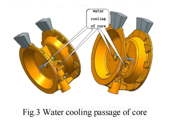
кольцевой фланец. С учетом усадки литейного стержня, как показано на рис. 3, подающий бегунок
1827 в толстой горячей точке, соединенной с литниковым затвором, открывается. Четыре сердечника полностью подают среднюю толстую деталь
за счет водяного охлаждения. Две бегунки установлены для подачи толстой бобышки гайки на кольцевой фланец, а усиливающие ребра вокруг
Ребра, расположенные по периметру, полностью подают фланец отливки.
Такая система подачи полностью и всесторонне охватывает горячую точку отливки, поэтому дефекты
усадочного отверстия и усадочной пористости можно эффективно избежать
Конструкция выпускной системы
Газоотвод рассматривает в основном два аспекта: выход газа из полости и из полости
угол заполнения.
Холодный затвор с газобарьерным свойством очень легко образуется в глухом углу заполнения, например в
верхняя часть полости и ребра жесткости. При проектировании технологического процесса необходимо обратить внимание на конструкцию вытяжки в этих местах.
при проектировании технологического процесса. Основные выхлопные отверстия литниковой системы двигателя располагаются так, как показано на рис. 4.
Рис. 4. На боковой стороне пресс-формы имеется еще одно отверстие, которое может быть выполнено в виде выпускного канала.
В процессе работы необходимо усилить условия выхлопа в этих местах. Центральное отверстие
центральное отверстие выполнено в виде подвижного выпускного канала, поэтому выхлоп может быть очень плавным. Усилить условия выхлопа
условия в выпускной пробке верхнего штампа, и тогда будут получены идеальные результаты.
Параметры процесса литья
На следующем рисунке (типичная схема процесса литья под низким давлением) показан
типичное управление процессом литья под низким давлением. Из шести стадий - подъем, заполнение, образование корочки, затвердевание под давлением
затвердевание, выдержка затвердевания и выгрузка затвердевания, третья стадия должна быть установлена в зависимости от потребностей и обычно для
в зависимости от потребностей и, как правило, для тонкостенных отливок эта стадия должна быть отменена или сокращена до минимума.
или сократить до минимума.

Назначение подъемного давления - добиться подъема жидкого металла к бегунковому затвору.
Благодаря большому объему воздуха, большому уклону сечения A - B и высокой скорости подъема, это позволяет эффективно
для повышения эффективности производства.
Давление подъема также называется давлением подвески, и разница между этими двумя видами давления заключается в том, что постоянное давление подъема не может быть постоянным.
разница между ними заключается в том, что постоянное давление подъема не может компенсировать потерю давления, возникающую при снижении уровня жидкости в печи во время работы.
уровня жидкости в печи в процессе производства. Уровень жидкости в печи на
начальной стадии заполнения формы изменяется динамически. Давление взвеси = давление подъема + давление
потери△P. Поэтому параметры давления заполнения пресс-форм можно стабильно поддерживать на определенном уровне,
при этом высота уровня жидкости в печи на начальной стадии заполнения пресс-формы остается неизменной.
Назначение давления заполнения заключается в завершении процесса заливки металлической жидкости в полость.
При определенной вентиляции, в условиях заполнения, низкое давление может снизить скорость заполнения, обеспечить
обеспечить полное удаление газов из полости, улучшить способность зазора штампа герметизировать жидкий металл и
зазора матрицы, герметизировать жидкий металл и песчаные жилы, уменьшить застревание матриц и процент брака по обожженным пескам.
Основное назначение давления удержания в настоящее время заключается в улучшении подающей способности литниковой системы.
системы. В общем случае, чем выше давление выдержки, тем лучше эффект.
Ниже приведены некоторые важные технологические параметры: давление подъема - 0,018-0,018 МПа;
давление наполнения - 0,03-0,05 МПа; давление наддува - 0,05-0,08 МПа; время наполнения
нагнетания составляет 10-20 секунд. Кроме того, время подачи воды составляет 30-100 секунд; температура пресс-формы для верхнего штампа 320 + 40
температура верхней пресс-формы 320 + 40 ˚C; температура нижней пресс-формы 350 + 50 ˚C; температура алюминиевой жидкости 710-77.
температура алюминиевой жидкости - 710-720 ˚C.
Анализ и контроль нестабильных факторов процесса литья под низким давлением
Нестабильные факторы процесса литья под низким давлением
Стабильность работы штампов зависит от стабильности параметров технологического процесса. Нестабильное управление процессом
обязательно приведет к колебаниям качества отливок. Современная технология литья под низким давлением имеет
недостатки в следующих трех аспектах: контроль температуры, скорость заполнения и давление заполнения.
Температурный контроль: в результате ограничения скорости передачи тепла от формы и
Периодическая смена условий нагрева и охлаждения затрудняет контроль температурного режима формы.
Поскольку существуют большие различия между началом и концом производства, температура нижней матрицы относительно ниже, а температура
нижнего штампа относительно ниже, а разница между верхним и нижним штампами невелика.
Кроме того, от ходового затвора до горячей точки, требующей подачи, градиент температуры значительно меньше
чем в конце производства. В результате меняются условия подачи, и трудно определить разумное время затвердевания отливки.
трудно определить рациональное время затвердевания отливки и скорость заполнения. Кристаллические структуры и
механические свойства отливок в разные периоды имеют большие различия[3,4].
Поскольку площадь теплоотвода в нижней форме значительно меньше, чем в верхней.
Нижняя форма имеет больше возможностей для нагрева, в то время как верхняя форма может только рассеивать и
поглощение тепла. Такие факторы, как многократно промытая печь выдержки, высокотемпературная печь, высокая
температура жидкого алюминия, а также непосредственный контакт с высокой температурой жидкого
1829алюминием в период затвердевания под давлением, могут привести к тому, что температура пресс-формы постепенно
постепенно приближается к температуре жидкого алюминия. С увеличением времени работы градиент температуры
градиент температуры между верхней и нижней матрицами становится все больше и больше.
Скорость заполнения: при каждой заливке штампа объем полости печи увеличивается на △V. Из
"PVT = постоянная" известно, что при фиксированных параметрах температуры заливки Т и давления Р
с увеличением объема V приток воздуха обязательно увеличится. [4]При постоянной скорости впуска
[4]При неизменной скорости на входе время на входе обязательно увеличится. С увеличением времени впуска скорость наполнения будет уменьшаться
уменьшается, либо фактическое состояние заливки задерживается. По мере того как кривая фактического состояния разливки на участке B---C
наклон уменьшается, точка C, время окончания разливки постепенно задерживается, как показано на рис. 5.
Если управляющий сигнал "корка затвердела", то в процессе разливки жидкого металла возникнет пауза, и качество продукции серьезно пострадает.
качество продукции серьезно пострадает[4].
Давление заливки: при каждой заливке печь опускается на △h, а давление заливки
уменьшается на △P. В течение всего рабочего процесса параметры давления заполнения матрицы находятся в динамическом падении.
динамическом падении.
Контроль температуры, выбор и регулирование скорости заполнения и давления заполнения при литье под низким давлением
литье под низким давлением
Контроль температуры: Стабильный контроль температурного поля является одним из основных условий
стабильности качества штампов. Выбор оборудования, конструкции и параметров должен быть контролируемым.